Boiler Feed Circuit
Boiler Feed Circuits
This outlines two patented fuel supplying and feeding methods located adjacent to the Boiler’s combustor. The two different schemes are applicable to burning coal, wood, Municipal Solid Waste (MSW), shredded rubber tires, shredded MSW (RDF), and other biomass fuels.
I. Storing and Distributing with Multi-Feeders Supplying the Boiler

Since it enables independently controlled Feeders, this equipment arrangement provides a more precise command of each of the individual burning zones. For example, the “Bed” and “Vapor Space” temperatures in the combustor. Any belt conveyors to “return” any of the over-fed fuel are optional and are not shown.
• The Surge Bin: Its function is to provide local storage to smooth out the fuel supply coming to it from the outside storage area. Most often this is an Activated Bin which vibrates as a complete entity. However, for the coal and wood, it could be a Bin Activator coupled with a static upper Bin, which would be less expensive. This Bin discharges into the inlet of the Fuel Distribution Conveyor. If needed, flexible connections are used to seal its inlet and outlet.

Fig. 2 – This strip chart shows the steadiness of the steam flow, total air flow, and steam pressure with this type of Boiler Feed Circuit.
This IVF unit would necessarily be “cycle type” operated to reliably discharge its full contents of storage. The flow down through the outlet will be a continuous supply to the Conveyor below even though this Bin is being turned on and off. Electrical sensors positioned at the inlet of the Conveyor automatically vibrate this Bin whenever more fuel is needed.
• The Fuel Distribution Conveyor: This Dust-Tight trough design distributes the waste fuels to all the grouped Metering Bins that supply each of the respective Boiler Feeders. It is a Vibrating Conveyor that might be built “upside down”. That is, the fuel’s conveying trough is on the bottom and the unit’s counterbalance is mounted above it. This enables the trough to more readily supply multi-outlets. Counterbalancing is always recommended to avoid nuisance vibration in the supporting structure.
When the conveyed fuel encounters a filled Bin, it passes over that outlet and moves down the trough to one in need of a supply. As the fuel passes over the filled outlet, it does not develop an appreciable downward force on the stored fuel below as would innately occur if a form of “Impelled Conveying” had been utilized.
This Conveyor should be powered by the “free force input combined with sub-resonant tuned springs” type of vibratory drive, which is commonly called the “Kinergy Drive System”. In addition to being very energy efficient, it offers more performance capability and operating flexibility than any other kind.
• Metering Bins: These are small storage bins mounted directly over the Boiler Feeders. Almost always they are “Activated Bins”. Flexible connections seal their inlets and outlets.
By electrical sensors located at the inlet of the Feeder below, they are automatically turned on and off and are vibrated only when necessary. This keeps the inlet of the Feeder below filled with fuel.
• Boiler Feeders: These are Dust-Tight trough design Vibrating Feeders equipped with the same patented Kinergy Drive System. To avoid nuisance vibration transmission, they are almost always counterbalanced. Flexible connections seal the Feeder’s inlet and outlet.
They have a full “zero to maximum range of feed rate (TPH) adjustment” in infinite steps, which enables them to markedly change their outputs. Since it is an electrical type of control, the response to a feed rate adjustment is very fast. They automatically follow a standard 4 to 20 milliampere d.c. signal provided to them by the Boiler’s program computer located in the main control room. In turn, that “PLC” is monitoring the Boiler’s combustion process.
The Feeder’s quick response over this optimum output range in conjunction with the combustion monitoring computer is the primary reason steam flow, steam pressure, and total air flow steadily and stay within acceptable limits. This is so even though the fuel is continually varying in both physical and thermal properties.
A minimum of three Feeders per the larger, utility type Boiler is typical when firing either the “Traveling Stoker Grate”, Vibrating Stoker Grate, or all the fuel inlets of the “Fluidized Bed” type of combustors. Five Feeders or feed points per Boiler have proven to be even better when close controlling of the individual “Bed” and “Vapor Space” temperatures in the Boiler are wanted.
II. Storing and Using the Distribution Conveyor as the Feeder
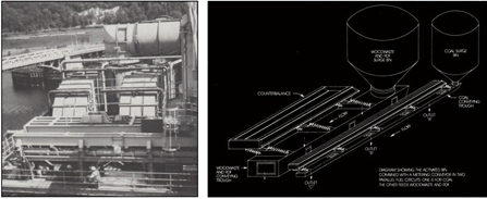
Fig. 3 – A “simplified” Boiler Feed Circuit. By using “distributed feed points per Boiler”, the Metering Bins and separate Feeders are eliminated.
If the Boiler’s individual temperature zones above the chosen Stoker Grate or Fluidized Bed do not need a high degree of individual controllability, then the Metering Bins and the Boiler Feeders described above can be omitted. The Surge Bin is retained to supply the “Fuel Distribution Conveyor”. The fuel entering this Conveyor’s inlet is reasonably sub-divided into the needed number of feed streams.
Consequently, it becomes a “Metering Conveyor” and is equipped with air-operated gates at each of its outlets. These discharge at all the appropriate Boiler feed points along the unit’s length. It is diagrammed and pictured in Fig. 3. As observed, it can also eliminate the “Return” Conveyors for any overfeed.
It has the advantage of simplifying the “Boiler Feed Circuit”, and it markedly reduces the equipment cost. However, it does sacrifice some measure of controllability of the “Bed” and “Vapor Space” temperatures in each of the “firing zones” of the Combustor. This Metering and Distribution Conveyor is automatically responding to the electrical control signal from the computer monitoring the Boiler’s Combustion Process. The identical “zero to maximum” output adjustment is available because it has the same Kinergy Drive System as the Feeders described above.
Design Features of the Kinergy Boiler Feed Circuits
Kinergy has the most advanced vibratory machine technology available. Our designs include the following:
• Durability: Each of the Vibratory Machines are built to last with an average of 20 or more years of productive use.
• Proven Performance: The simple design and best performance rating make the Kinergy Vibrating Conveyor and Feeders the best choice.
• Energy Efficiency: Since the Bin Activators and the Activated Bins are “cycle” type operated, the power consumed is only about one-third of the motor’s horsepower or kilowatt rating. The intermittent “on/off” cycle has a “root-mean-square” (RMS) evaluation that reveals this power reduction.
All the Conveyors or Feeders utilize the Kinergy Drive System, which is the most versatile and energy efficient drive available.
This drive is a combination of a free force input from an A.C. type electric motor with the output of sub-resonant tuned springs. When the applied load increases, the springs inherently drive harder. It maximizes the use of “Kinergy”, which is defined as the kinetic energy developed by a spring’s motion during the drive portion of its cycle.
• Dust-Tight Construction: For the Conveyors and Feeders, our integral Dust-Tight design is recommended.
• Self-Cleaning: All the Activated Bins, Vibrating Conveyors, and Feeders are inherently self-cleaning of the material being fed, which makes them attractive when dealing with sanitary applications or when material contamination is to be minimized or avoided. Sanitary polishes, as well as the various coatings, are attainable.
• Larger Dimensions: Since the Kinergy Drive System spreads or distributes the vibratory dynamic forces, the diameter or length and width dimensions are not restricted as they would be if it was concentrated at one point. This is the reason Kinergy Driven Uni-directional Vibrating Conveyors and Feeders are standardized in diameter or widths to 18 ft. and the respective lengths as required.
• Simple Electrical Control: By taking advantage of the inherent adjustable output, the Kinergy Vibrating Conveyor and Feeder can have their respective operating stroke and frequency automatically and repetitively “pulsed”.
• Reduced Sound Levels: All these Vibratory Machines operate very smoothly and quietly. Typically less than 80 dBA.
• Low Maintenance: By the use of components specifically designed to endure the vibratory action, maintenance requirements of all these Vibratory Machines are minimal.
• Interchangeable Components: Most of the component parts of the Kinergy Vibrating Feeder are interchangeable with other Kinergy Driven units even though their functions may differ. These common components extend to Screens, Conveyors, Fluidized Bed Coolers and Dryers, Spiral Elevators, and the various types of Foundry units. This reduces the number of spare parts required.
• Counterbalancing: All Kinergy Driven Feeders are dynamically “counterbalanced”. This is inherent in their modern design.
Kinergy’s engineers are very knowledgeable of both the principals of Induced Vertical Flow and Induced Conveying. To learn more about Kinergy’s Boiler Feed Circuits, please contact us at 502.366.5685 or download Kinergy’s Technical Paper entitled “Storing & Dischargarging, Distributing & Feeding ‘Waste Type Fuels’ to the Combustors of Boilers”.